Building a Bluetooth Macro Keyboard
I’ve been wanting a ‘macro keyboard’ for a while - a custom keypad that lets me save special characters or key sequences that I use frequently, then play them back at the push of a button. You can buy them, of course, but for projects like this, I always like to try and do it myself. It’s a fun learning experience, and using tools you built with your own hands feels so much more satisfying than buying them.
My early vision for this project was to have something that plugs in via physical USB. However, none of my ‘go-to’ standard microcontrollers - the ones I have lying around in my workshop - have USB hardware on them. I’d planned on getting my hands on a board that does have USB support, e.g. the Raspberry Pi Pico, but with how busy I’ve been with my degree, I never got around to it.
Today, though, I had a realization: I remembered that bluetooth keyboards exist! I’m somewhat familiar with the USB HID spec (which is what USB keyboards use to communciate with the host),1 but despite having dozens of ESP32s lying around, I’ve never actually looked much into the bluetooth side of things. It’s possible it might even be easier, thanks to some quirks in the USB implementation!2 Since I already have all the components I need lying around, I figured this would make a great project to get me back into PCB layout and firmware design.
The Plan#
I have a tradition of giving my projects serial numbers, to make it easier to label things and because I think it sounds neat! I’m dubbing this project PASF-001, codename “Clover.” My plan is to do some simple proof-of-concept prototyping on a breadboard, and then order a proper PCB for the final product. It’s the sort of thing I could do very quickly if I could put all my time into it, but since I have a lot of paper-writing to do this quarter, I’m estimating a timeline on the order of a few months.
Hardware#
The microchip I’m using for this project is the ESP32-WROOM-32E. It’s not the latest and greatest, but I have a bunch around the lab and it’ll be more than enough for this project. It supports Wi-Fi, Bluetooth, and BLE - I’ll be using the latter for the keyboard itself, but the Wi-Fi might also be useful to make an easy, web-based configuration tool for setting up macro functions (more on that later).
Once I’ve finished my prototyping and laid out the final PCB, my plan is to have the boards manufactured and (some of) the parts placed by JLC - I’ve worked with them before, and they’ve been quick, responsive, and quite affordable. Their SMT assembly parts library is fairly comprehensive, but they don’t tend to stock the ESP32, so I’ll need to put the controller on manually. With a heat gun, it’s not too bad.3
Here’s a quick circuit sketch of the design:4

The keys are set up in a standard switch-matrix design, to save on I/O pins. I reserved one row of buttons for a ‘page select’ system, which would allow the user to switch between five different 25-button ‘pages’ - that way, you could have one page for quickly typing in math notation, another for video game hotkeys, etc.
Also, note the pin assignments on the ESP32. They might seem a bit random, but I’m actually trying to think ahead to when I implement this in hardware. To see why, take a look at Figure 3 in the ESP32-wroom-32e datasheet:
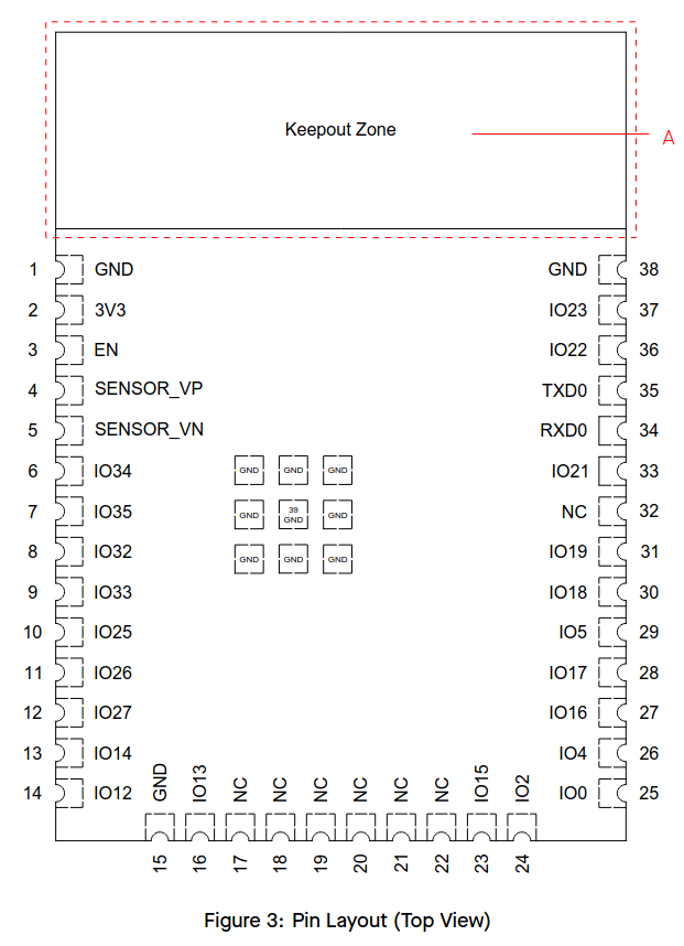
Note how, if you match the row and column labels to their physical pads on the PCB, each one lines up nicely! This will make it easier to route the hardware later on during the PCB design process.
Battery#
Of course, if this was a USB keyboard, battery power would be an unnecessary concern; however, since we’re already connecting over bluetooth, it seems a bit silly to make our users plug the device in to power it. I haven’t worked with battery-powered devices before, so this is a great opportunity to learn! After a bit of research, I decided to use the Microchip MCP73831 charge management controller to manage the battery charge. It only supports single-cell batteries, but a keyboard shouldn’t take that much power, so single-cell batteries should be more than enough for this project.
Firmware#
The ESP-IDF SDK is pretty easy to work with, but I’ll need to do some research to see exactly how the Bluetooth HID standard works. I’m hoping the standard supports proper unicode input rather than just scan-codes, but given the lack of support in the USB HID standard, that’s far from certain. If it doesn’t, then we’ll have to see if there’s some way of detecting the OS through Bluetooth.
Next Steps#
I plan on posting about this project whenever I get the chance to make an update. Once it’s done, I’ll make and post a full write-up.
Footnotes#
-
Most of my USB knowledge comes from the book USB Complete, Fifth Edition, by Jan Axelson. ↩︎
-
The USB HID keyboard implementation was designed a long time ago, and it shows. It can send a specific set of ‘scan codes’ that the host OS knows how to translate into keys (see the HID usage tables, section 10), but as far as I know, there is currently no way to send arbitrary unicode in a platform-independent way! If I wanted a keyboard that can type, for example, mathematical operators like ∴ or ∑, I would need to have the keyboard send a platform-dependent shortcut sequence (Alt-X for windows; Ctrl+Shift+U for some linux implementations), or I would need to write a custom kernel driver for my device. ↩︎
-
It can be done without a heat gun, as well, but it’s a bit trickier. Use a very narrow-tipped soldering iron, and be careful to keep the chip flat against the PCB and well-aligned with the pads while you’re soldering (maybe even using a clothespin or similar method to keep it in place). It’s also a good idea to start by soldering two pins on opposite sides of the chip, so that those two connections can help keep it aligned and in-place as you solder the rest. ↩︎
-
I use KiCAD for most of my PCB design. It’s open-source, and these days, it’s quite full-featured! ↩︎